When One + One ≠ Two:
How to enhance optical blocking using multiple filters
When signal light is very precious, any background light that reaches the detector of an optical system can greatly compromise signal to noise ratio. If the signal is low then the background must be maintained at an even lower level and so background light must be minimized. For instance, in a Raman analytical system only one in a million photons will be Raman scattered so each must be captured an analyzed from among the 999,999 non-Raman scattered photons.
In such applications, extremely high levels of blocking are necessary outside of the signal band of interest. Where a typical high-end system may specify an out of band blocking with an optical density of 6 or more (OD>6 or <0.0001%) some systems seek OD>8 or even OD>10. These levels are difficult, in some cases impossible, to manufacture, test, and guarantee with an individual optical filter.
This can lead to the proposition of using more than one blocking filter – the logic being that if one filter provides OD>6 then two filters together will provide double the blocking and achieve OD>12 (or at least close to this level). However, the way in which the blocking is achieved using multi-layer thin film filters, that is via reflection and not absorption, makes this a flawed argument unless there is careful consideration and set-up.
One plus one does not always equal two.
Case 1: Two Filters in Parallel at Normal Incidence
The typical approach is to suggest two filters arranged in series with the normal to the filter surface colinear with the incident beam. This case applies to coatings on the front and back surface of a single substrate, or multiple filters in series.
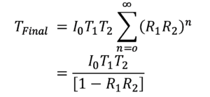
Handling the multiple reflections between the coatings, the solution to this arrangement is a geometric series with functional form
where I0 is input light intensity, T1, T2, R1, R2 are the transmittance and reflectance of each filter respectively
Example – Filter 1 and filter 2 each have OD3 blocking (R=0.999). The solution to Tfinal is OD3.3
Case 2: Two Filters in Parallel at Non-normal Incidence
In this scenario the filters can be arranged at an angle such that the reflected beam does not reflect back along the incident light path and is effectively removed or “walks-off” from the beam path (with appropriate stray light mitigation).
The solution to this arrangement is
TFinal = I0T1T2
Example – Filter 1 and filter 2 each have OD3 blocking (R=0.999). The solution to Tfinal is OD6
In “Case 1” doubling the number of filters is far from doubling the net blocking achieved but in “Case 2” the use of two filters does achieve the doubled blocking desired. However, it is important to note that for “Case 2” the filters have to be designed and manufactured with the intended angle of incidence in mind. If “standard” blocking filters designed for use at normal incidence are used the increased angle will result in both a wavelength shift and a relative splitting between polarizations of incidence light so would not be a recommended solution. Also, the reflected light must be appropriately managed so that it does not contribute to background within the system.
In summary, one plus one does not always equal two when it comes to optical filters and blocking but can be made to do so with careful design and use considerations. As always, our technical sales and applications engineering teams here at Iridian Spectral Technologies are available to consult with and discuss options and considerations to ensure that the filters we deliver achieve the desired functionality in your application.


