Coarse Wavelength Division Multiplexing (CWDM) filters are designed to multiplex and de-multiplex wavelength signals in metropolitan, access and enterprise networks and for Cable TV applications. In addition, they are often used to provide the wireless backbone for the latest 4G wireless networks (LTE). They are a low cost approach for systems that use non-cooled laser sources, and are an alternative to more expensive DWDM components based on 100 GHz or 200 GHz channel spacing. CWDM channel filters are used to isolate a specific wavelength channel whereas CWDM channel splitters are used to isolate a band of channels.
CWDM Channel Filters
A CWDM channel filter’s purpose is to separate a single channel’s signal from a group of signals. This is realized by allowing the wavelengths of light corresponding to the CWDM channel filter to pass while all others are reflected. This same filter may be used to add a channel’s signal to a group of other channels.
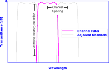
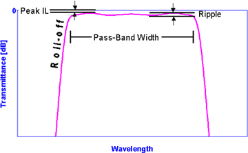
The critical specifications of a CWDM channel filter are peak IL, ripple, pass-band width and isolation. The pass-band width and isolation points must be matched to the channel spacing of the of the CWDM system. The latest standard proposed by the Full Spectrum CWDM Alliance (FCA) is a channel spacing of 20 nm starting from 1271 nm up to 1611 nm. The FCA proposed a pass-band width of greater than 14 nm for all of the 18 channels.


Center Wavelength [nm]
This is the average or mean wavelength based on two points on the curve at the same transmittance level. A typical level is at Full Width Half Maximum (FWHM) or -3 dB. At this level any ripple or other pass-band defect will not effect the center wavelength calculation.
Pass-band (PB) [nm]
This is a region of high transmittance. It is usually specified by a pass-band width, peak IL and ripple. The pass-band width is specified in nm at a certain transmittance level relative to the peak transmittance.
e.g. PB @ -0.3 dB: 1530 nm-1570 nm
The pass-band can also be specified by defining a center wavelength (CWL) and pass-band width.
e.g. CWL @ -0.3 dB: 1550+/-0.5 nm
PB @ -0.3 dB > 40 nm
Isolation
This is the difference between the minimum transmittance within the channel filter’s passband and the maximum transmittance of the same filter within another channel’s passband. Typically channels immediately adjacent the passband are less isolated than non-adjacent channels.
Polarization Dependent Loss (PDL) [dB]
Polarization Dependent Loss (PDL) can be defined as the maximum change observed in transmittance or reflectance at a given wavelength as the light is cycled through all possible polarization states. The PDL can be calculated based on the difference between the s- and p-polarization states of light, i.e.,
Transmittance PDL(l)[dB] = Ts(l)[dB] – Tp(l)[dB]
Peak Insertion Loss (IL) [dB]
Peak insertion loss is the value of maximum transmission in the passband.
Peak IL = T(lPeak) [dB]
e.g. Peak IL < 0.1 dB within passband
Ripple [dB]
Usually the passband ripple is specified as the difference between the maximum and minimum transmittance in the passband width (see above figure). Note that this passband ripple is different from that of a substrate etalon ripple.
Reflectance Isolation [dB]
This is difference between the maximum reflectance in the pass-band and the minimum reflectance in the reflect-band. The minimum reflectance in the reflect-band is very often close to 0 dB so that the reflection isolation is typically dominated by the maximum reflectance in the passband. For filters with no absorption, the transmittance and reflectance must add up to unity. Hence, there is often a relationship between the specified reflection isolation in the passband and the sum of the peak IL and ripple in the passband, i.e.,
If the reflection isolation is specified to be -15 dB (corresponding to a reflectance of 3.2%), then as T+R =1, the minimum transmittance in the passband is given by T=100-3.2=96.8 % which is equivalent to a 0.14 dB transmittance loss. Hence, to achieve a reflectance isolation of -15 dB, the transmittance loss must be less than 0.14 dB. Note that if a minimum allowed transmittance loss of 0.2 dB is specified along with a reflectance isolation of -15 dB, then the overriding transmittance loss to achieve the necessary reflectance isolation is 0.14 dB.
CWDM Channel Splitters
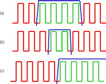
In an 8-channel CWDM system, a channel filter will transmit 1 channel and reflect all other channels but a CWDM channel splitter is typically designed to transmit either 2 or 4 CWDM channels and reflect the remaining channels. Figure A below shows Iridian’s standard channel splitter filters for the upper 8 channels. Each of the channel splitters, drawn in blue, shows either 2 or 4 passing channels in green and the remaining reflecting channels in red.

Figure A. (a) 4×0 CWDM channel splitter, (b) 2×0 CWDM channel splitter and (c) LPF8-C2-C1 CWDM channel splitter.
Channel splitter customization
Depending on the needs of the system designer, the center wavelength of the 2×0 and the 4×0 can be customized to pass different channel groups. Similarly the position of the edge of a short pass or a long pass channel splitter can be customized. The simple naming scheme detailed in figure B can be used to describe any standard and customized edge pass channel splitter as shown in the example of figure B and C.
LPF8-L2-L1

Figure B: LPF8-L2-L1 CWDM channel splitter.
SPF16-E5-S1

Figure C: SPF16-E5-S1 CWDM channel splitter
